
|
Home Sitemap All Articles Glossary |
Cyclic
and Symmetric Boundary Conditions —
Ways to Reduce the Size of Numerical Models
by George Moore, PE, Fluids
& Heat Transfer Manager, J Tarpoff Corp, 513-932-9777 gmoore@tarpoffmoore.com
The "brute force" method of modeling in which the entire component is explicitly represented can lead to large time consuming models that are often not warranted. One method of reducing the analysis domain is to look for cut planes that will allow a section of the component to accurately represent the entire component. The cyclic and symmetric conditions provide the cut planes that allow reduction of the model size.
Axisymmetric Modeling
The greatest reduction in the required calculation domain is when the component
can be modeled as two-dimensional (2D). One example of this would be a flywheel
with a continuous web (Figure 1). Any cut plane that passes through the axis
of the flywheel would show the same cross section, and this is referred to an
axisymmetric condition. The loading on a flywheel is due to the rotation which
means that the load will vary in the R and Z directions but not in θ. Mathematically,
axisymmetry must meet the conditions A(θ) = constant. A similar condition
can also occur in non-rotating structures although not as common. An example
of this would be a vertical fin heat exchanger attach to a horizontal heat source.
Since almost all of the heat transfer is from the sides of the fins, the end
effects are negligible and the system becomes 2D. Again, the situation involves
one coordinate direction in which the defining parameters do not vary.
The 2D modeling requires only that the mass properties and surface areas in the direction perpendicular to the cross section be correctly represented. Most commercial finite element and finite difference analysis programs have features built in to handle rotated geometries and unit depths. Note that when applying boundary conditions to a unit depth model the loads must be applied on the per unit basis.
Symmetry Boundaries
When 3D modeling is required, symmetry planes allow the use of a section of
the component with minimal effort to apply boundary conditions on the cut plane.
A simple definition of a symmetry plane is a plane at which the component mirror
imaged. A simple example is a simply supported beam of constant cross section
with a uniform load applied. The model of the beam can be cut at the center
and the only constraint need at the cut plane is that deflection is not allowed
in the direction normal to the cut plane. Another common example of the use
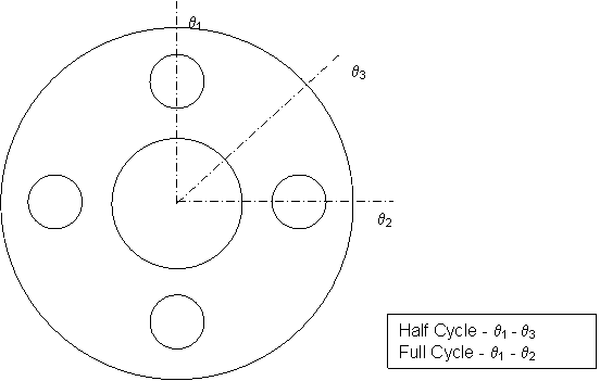
of symmetry is a bolted piping flange that can be model by a sector cut through
the centerline of a bolt and either through the halfway point between the bolts
(half cycle) or through the centerline of an adjacent bolt (full cycle) (Figure
2).
The mathematical definition of symmetry is that the partial derivatives in the coordinate normal to the plane exist, are continuous, and are equal to zero (∂A∂x = 0) and A(x + δ) = A(x - δ). Keep in mind that for symmetry to exist the conditions must be met for the geometry of the component, the material properties of the component, and the loads applied to the component.
Boundary conditions for symmetry cut planes are very simple. The cut face is not allowed to defect out of the plane of symmetry. Heat transfer modeling at a symmetry plane is thus handled by placing no boundary conditions on the cut plane. Other BCs should be applied as actually occur in the section being modeled.
Cyclic Boundaries
The third cut plane condition that can be used to reduce that solution domain
is a cyclic condition. This refers to a component that has a repeated pattern
in the geometry and loading but does not meet that mirror image requirement
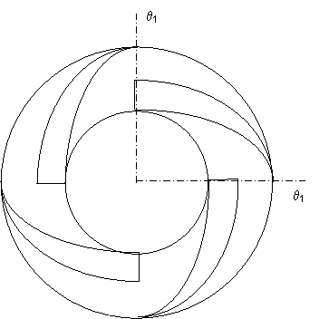
necessary for symmetry. An example of the cyclic condition would be a swept
vane pump impeller (Figure 3). The sector being model must equal the angle swept
by pattern, in the impeller case one vane.
For the mathematical definition of a cyclic condition assume that one cycle is defined by a sector that sweeps from θ1 to θ2. The cyclic condition can then be met if A(θ1) = A(θ2), ∂A/∂θ1 = ∂A/∂θ2, and the derivatives are continuous. A connection between the cyclic condition and the symmetry condition should be noted. A full cycle symmetry condition meets all the requirements for a cyclic condition plus the added restriction of ∂A/∂θ1 = ∂A/∂θ2 = 0. Thus, symmetry is more restrictive subset of the cyclic condition.
Since the mirror image as seen with symmetry does not exist with cyclic conditions, the handling of boundary conditions at the cut plane becomes more complicated. At every R, Z location, the variable parameters on the cut planes must be held equal to each other. Most commercial analysis codes either provide internal capability to couple the cut planes or allow input of user defined transfer functions. As with symmetry, other BCs should be applied as actually occur in the section being modeled.
These three conditions if properly applied can significantly reduce the size of an analytical model with no reduction in the accuracy of the results. Other methods exist for simplifying analytical models but most result in certain amount of degradation to the results.
 |
 |
|
Figure 1 - Axisymmetric Flywheel |
|
 |
|
Figure 2 - Symmetric
Bolt Flange |
 |
|
Figure 3 - Cyclic
Pump Impeller |
About the author:
George Moore, PE has performed detailed heat transfer analysis on military and commercial jet engines for more than six years. Prior to that, he spent thirteen years modeling and analyzing heat transfer and fluid flow loss of coolant scenarios of US Naval nuclear power plants for the Bechtel Bettis laboratory (formerly operated by Westinghouse Electric).